Project overview
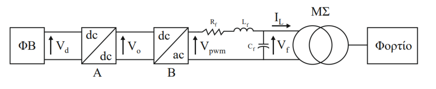
This project focused on the design and MATLAB/Simulink simulation of a two-stage power conversion system for a photovoltaic installation. The design combined a DC–DC boost converter, a single-phase full-bridge inverter, an LC output filter and a step-up transformer, with a 52–60 V PV input and a maximum converter output of 3.5 kW.
The work included analyzing converter operating conditions, sizing inductors and capacitors, comparing MOSFET and IGBT switching losses, and checking calculated component stresses against simulation results.
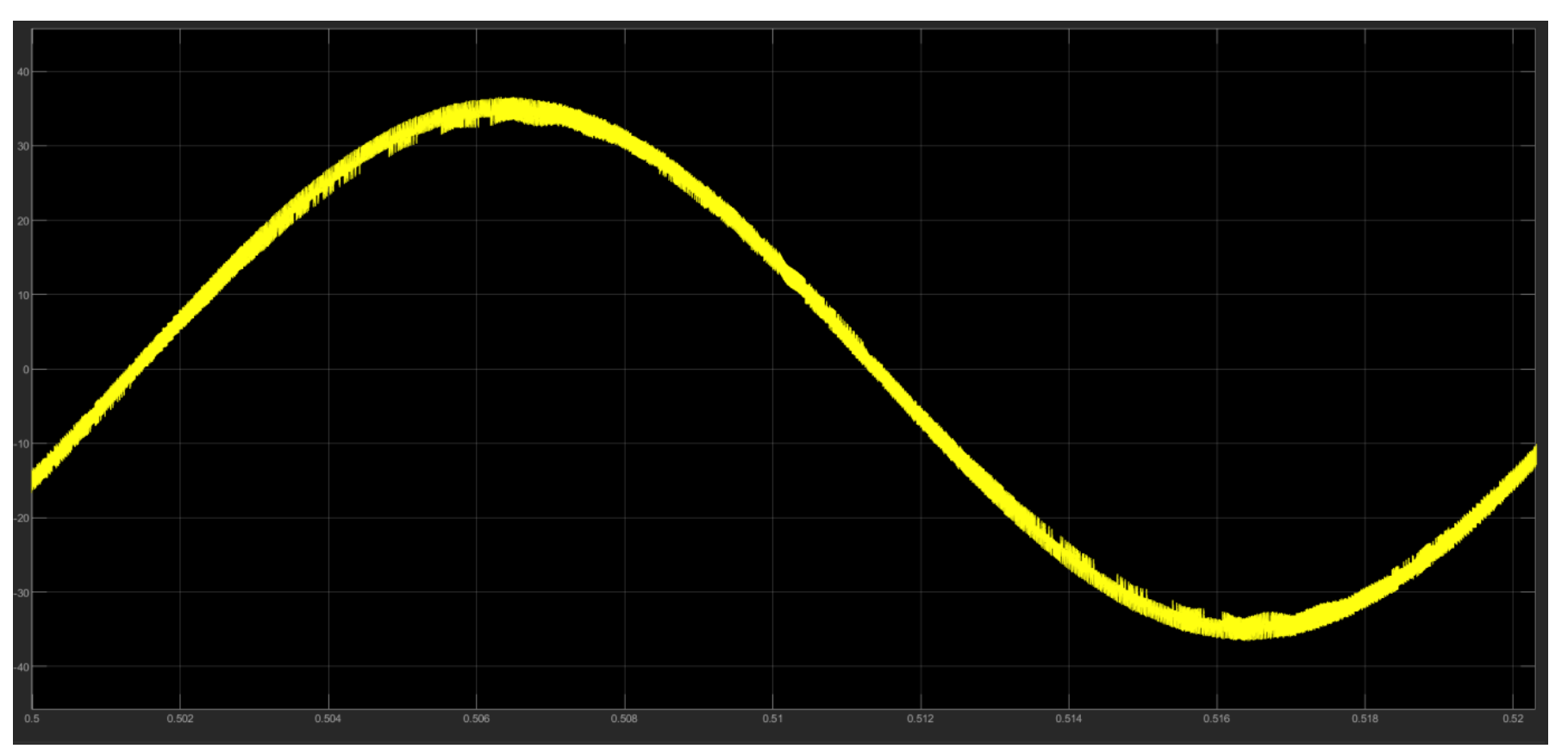
For the inverter stage, the study compared unipolar and bipolar PWM under different loading conditions, examining harmonic distortion and power losses. It also simulated a grid-connected single-phase inverter using variable-frequency hysteresis current control. One tested configuration achieved 3.76% output-current THD against a 4% design limit, illustrating the trade-off between harmonic distortion and switching frequency.
Selected figures